
Crossbar
Homebrew 4x4 LED matrix
A few years ago, when I finally got around to learning PIC programming, I decided to I wanted to create something that would run LED animations on a small 4x4 matrix. I liked the idea of the small 4x4 size because I was starting with a PIC 16F628A. This chip can not directly control the 16 lines necessary for an 8x8 matrix (unless you get fancy). Also the 4x4 arrangement just seemed easier to work with in terms of coming up with different patterns. And the patterns would require less memory. One frame on a 4x4 matrix is 16bits or just 2 bytes, but on an 8x8 matrix, a frame would require 8 bytes.
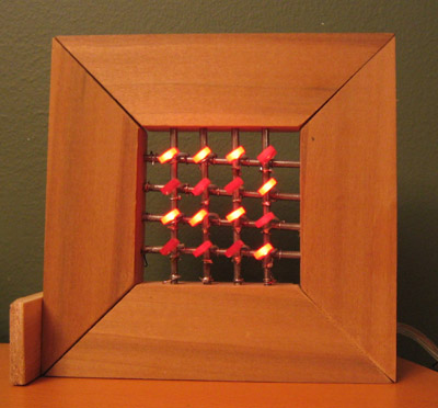
I also knew that I did not want to leave this on my workbench. Instead, I wanted it somewhere else in the house. Somewhere where I could see it often and where anyone visiting might notice it. To me this meant that it couldn't just be on a PC board or a breadboard (where most of my projects are). I got the idea of building a small frame with horizontal and vertical bars. These bars would be the rows and colors of the matrix, and I would solder an LED at the intersection of each one. This has worked reasonable well. The problem, I found, is that steel is not the best metal for this since it has rusted slightly and has trouble holding onto the solder. But still, it has been running for about five years. Originally it was in the dining room, but, since we moved about two years ago, it has been in the kitchen, on a small shelf. Most people don't comment on it, a few ask about it, and one thought it was reading her mind.
Once I had it had it built, I then spent a lot of time coming up with as many different animations as I could think of. This was really fun. The video shows almost all of them. Some of the animations are described in the code frame-by-frame, as you might imagine. But for others, I added code that would allow me just to list the LEDs by number that would light up in sequence. These path-style animations saved a lot of memory because instead of needing two bytes to describe a frame, I only needed half a byte to specify the next LED in the path. There are also some animations described procedurally (for lack of a better term). For these animations, each step is described as an action, such as invert frame or invert center. This method was my original plan, but I found that it was not as interesting as I envisioned, and the code for all of the procedures took up too much memory. I will talk in detail about the theory behind each of these animation styles in a later post.
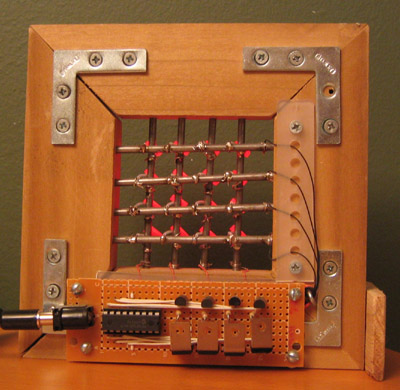
One of the things you might notice in the picture of the back is the strange choice of transistors. This is what happens when you don't know what you are doing. I hope since then I've learned a little more about the difference between PNP and NPN.
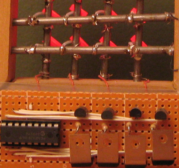
Here are pictures of the front, back, and some detail. I also learned that there is a big difference between thinking of building a small square frame and actually building a frame that is square.
Blog posts
Original
Crossbar: A Homebrew 4x4 LED MatrixElsewhere
Make:Zedomax
Downloads
PIC Assembly, HEX file, and EAGLE filesUpdates
Resistor Information: In the version I actually built (pictured above), I don't have any resistors between the PIC chip and the transistors, and used 220 ohm resistors between the 2N3904 transistors and the LED columns. This has been working great. From what I read in the Microchip docs, they recommend 2K resistors between the PIC and the transistors, so I have been doing that in my new designs. For the resistors between the transistors and the LED columns, you want (5v - V.led)/(I.led). If the drop (V.led) of the LED is 2v, and the current (I.led) is 20ma, then R should be 150 ohms. This is the most conservative number. Since the LEDs are multiplexed, you should be able to drive the LEDs with more current. Check the specs. I also recommend building it on a breadboard first. (June 4, 2008)
Regulator and Power-supply: If you have a regulated power supply, then you don't need the LM7805 or the capacitors. This is what I am using in the pictures above. (June 4, 2008)
Fixed Row Control: I updated the zip package with a fix for row control. The previous code was using active-high for the rows when it should have been using active-low. (June 4, 2008)
LED Test Application:I included a version of the application that will test each LED, then light each row, then light each column, then light all LEDs. The assembly is the same (look for the line that says "#define LED_TEST_BUILD") (June 4, 2008)