Simple LED Animation Kit
Introduction
The simple LED animation kit is designed to control up to twelve individual LEDs or groups of LEDs with a series of different animations using a PIC16F628A. The goal is to provide flexibility in selecting LEDs and creating a lighting arrangement.
The features are
- Control of 1 to 12 LEDs
- Repeating animations sequences
- LEDs can be individual LEDs or groups of LEDs
- Transitions can be immediate (no transition), gradual, or have a history (aka 'NightRider')
- Wiring can be common anode or common cathode
- LEDs with a voltage drop greater than 5v are supported
- Schematics for wall-wart designs and for battery designs
- Schematics for all-in-one designs (LEDs on the PCB) or LED off-board designs
- Many pre-programmed animations designed for different configurations (circle of LEDs, line of LEDs, bi-color LEDs)
The video shows five different configurations:
- a 3x3 grid ("Domicile"),
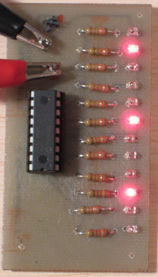
- a straight line of twelve (two are shown: one is done in red, the other in green)
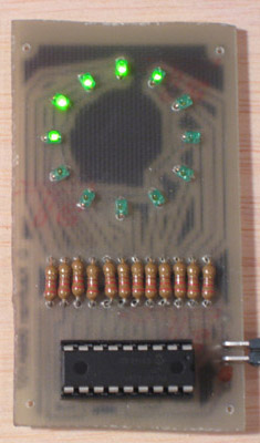
- a circle of twelve,
- three sets of six bi-color LEDs arranged in a triangle ("NewDimension"),
- a multi-segment front panel LED from an STB (two are shown: one is green and the other is blue) ("Roundabout")
Each of these use a different set of animations, where each animation is created or tailored to the count, color, and arrangement of the LEDs. Also, all of these different projects are described later on this page, with pictures of the front and back of most of the boards.
Features
Control of Up to 12 LEDs
The code is designed to support up to 12 LEDs. These LEDs can be connected to the PIC through a resistor, if the current and voltage needed is below the levels that the PIC can support (about 20ma per pin, 200ma total, source or sink; 5v). Or the PIC can be connected to NPN or PNP transistors to control greater currents or voltages.
Repeating Animations Sequences
The code is designed to cycle through all of the animations, restarting at the beginning after completing the last. And each animation can have its own speed, style, and repeat count. This is described in detail on Dispatching page.
Control Individual or Groups of LEDs
You can easily control more than one LED per pin of the PIC. In the NewDimension project, each pin controls three LEDs. For this type of arrangement you would typically use a transistor to switch the LEDs, to limit the current going through the PIC.
Transitions
Each animation can have it either an immediate (no transition), gradual, or history (aka 'NightRider') transition style. This will be described in detail on the Transitions page.
Common Anode or Common Cathode
A single #define at the beginning of the application allows you to specify "active high" or "active low" control of the LEDs. This is convenient because the LEDs you have might already be wired a specific way, especially if they are in a single package. This is the case for the front panel LED used in the Roundabout project and for the red/green bi-color LEDs. Also, if you are using LEDs that have a voltage drop greater than 5v (the supply voltage for the PIC), it is more convenient to write the LEDs as common anode, connected to the LED supply voltage and use a NPN transition to switch the negative side of the LEDs. For active high, you can wire the LEDs as common anode and use NPN transitions to control the current at the cathode. For active low, you can wire the LEDs as common cathode and use PNP transitors to control the current at the anode.
LEDs with Greater than 5v drop
In the Domicile project, the voltage drop for each LED is ~6v. To support this I connected the positive sides of the LEDs together to the supply voltage, used an 'active high' configuration of the software, connected NPN transitors to the PIC, and used a 7805 voltage regulator to limit the voltage to the PIC.
Schematics
Wall-wart and Battery Designs: In the downloads section, below, there are schematics and board designs where the LEDs can be soldered directly to the PCB, either in a straight line, a circle, or using that custom LED. Also, there is a schematic provided that includes a 7805 regulator to limit voltage from a wall-wart power supply
All-in-One or Off-board Designs: The wall-wart schematic also does not include any LEDs, so you are not limited to a predetermined arrangement on the PCB. You can also use the linear arrangement of the battery-powered design in the same way.
Many Pre-Programmed Animations
There are many different animations included in the source code. These are designed for different configurations (circle of LEDs, line of LEDs, bi-color LEDs).
Sample Projects
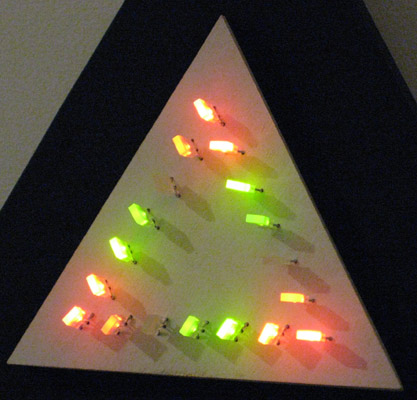
NewDimension
This project uses each pair of pins from the PIC to control one red/green bi-color LED, providing control of six LEDs. These LEDs are repeated three times, once for each side of the triangle. It might seem that you can not do too much with six LEDs, but that is not true. Between the triangular arrangement, the red, green, and yellow color possibilities, and the transitions, it is possible to create a large number of different animations. In the current code, the animation sequence takes 10 minutes to repeat.
The picture here shows the project built on a two-level triangular base hung on the wall.
See the upcoming NewDimension project page.
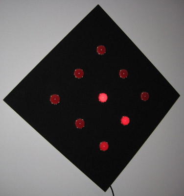
Domicile
This Domicile project was inpired by a desire to use 20mm diameter LEDs that I bought. These LEDs have a very even glow across their entire surface. I decided to create a 3x3 arrangement on a board that is 12in x 12in and to hang the board on a diagonal. With large size of the LEDs and the final project, I was interested in creating more gradual animations. It might not be clear in the video, but most of the transitions in this project are smooth. That is, the LEDs don't just turn-off, but fade from on to off or off to on.
The pictures here show the front, hung on the diagonal, the back, and a close-up of the PCB.
This is another one of the my projects that is simply on all of the time hanging in my office.
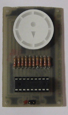
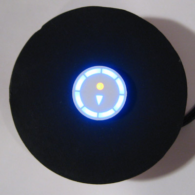
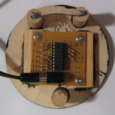
Roundabout
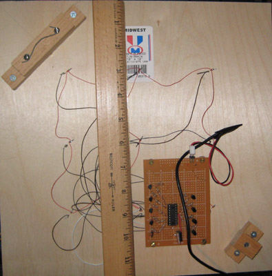
This project started when I found an LED that was part of the front panel for a STB (set-top box). I was particularly pleased with the circular arrangement of the eight LEDs around the edge. I decided to create SLAK when I knew I wanted to make a project with this LED and the Domicile project at around the same time.
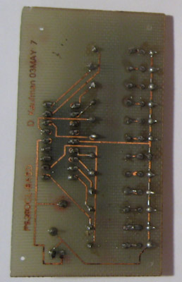
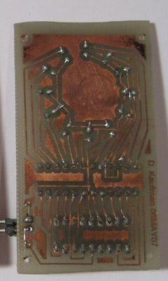
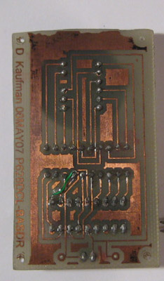
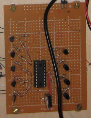
Small Design Boards
These boards represent my first attempt at making PCBs at home (using this method). I created the boards to make it easier to develop different animations, without having to use a breadboard all of the time. Also, these boards can work with either a 5v power supply or three AA batteries.