
Animated LED Pyramid
Overview
Looking for something to do with the thousand LEDs I bought from Electronic Goldmine, I decided to make a small pyramid. It reminds me of the Sol LeWitt sculpture, but on a much smaller scale. The LEDs are nearly cubes, so they stack nicely. The twenty-five LEDs in the pyramid are wired as a 5x5 matrix, and each LED can be controlled individually using a PIC16F648. I also extended Animator, my animation editor application, so it can be used to edit the animations.
Leave comments and question on the blog post.
Downloads are available at the bottom of the page.
Larger photos available on Flickr
Details
Getting Started
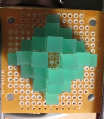
I mentioned in an earlier post that I bought a bag of one thousand square LEDs. These LEDs are little cubes, 5mm x 5mm x 5mm, with the top being more diffuse than the sides. I particularly like the view looking down at a corner, because this shows three sides at once, all showing the glowing die in the center. In another post I also showed these LEDs arranged in a diamond, as a way to highlight this corner view.
These LEDs are not perfect cubes. They have small flanges or edges on two sides. What I noticed is that if I have two LEDs about 5mm apart (stuck in a perfboard 0.2in apart) that I can put a third sort of above and on top of them. I realized I can extend this idea. Starting with the diamond arrangement, I decided to add another smaller layer. This was resting on top of and inside the first layer. Then I added another layer. At this point there was room for just one more LED. When it was all done, I had a small pyramid made of 25 LEDs. These were all just placed in a small perfboard without any solder or glue, and, after a moment, the pyramid collapsed.
So at this point it was just an idea. I was not sure how to build it, how to wire it, or even, really, what to do it. I thought it would be nice if I could individually control each LED, but I was not sure how.
Then I realized with 25 LEDs I could wire them as a 5 by 5 matrix. This would give me individual control of each LED. I also realized that I has just the platform for controlling a 5x5 matrix, my earlier FiveSquare project. And, the icing on the cake, I knew I could extend my Animator application to support the new arrangement.
So there were three things to do: extend Animator, create the LED pyramid, and figure out the wiring. One consideration that affects all of these is the LED numbering. Which LED is number 1, which is number 2, etc? This also answers the question about the orientation: which way is up?
Animator
More out of curiosity then anything else (I still was not sure I was going to build this) I decided to add the Pyramid layout to my LED animation editor, Animator. Once before I used the FiveSquare platform as the basis for a new layout. That time it was for my LED Pumpkin project. One of the things I did for the pumpkin layout was to use a table to list the position of each LED. I knew if I started with that file that it would be very easy to create the pyramid layout. I copied the pumpkin source code file, rename the file and the routines in it, and added it to the project.
The next step was more important than I realized. I changed the led positions table. I decided that the "northernmost" LED would be number 1. The leftmost LED on the next row south would be number 2, with 3 and 4 also on that row. The next row would start with 5, the next row with 10, and the new with 17. This continued up to the southernmost row, with the single LED in this row being number 25. Why was this significant? Because it meant that the LEDs has to wired into a matrix that corresponded to the numbering. LEDs 1 thru 5 had to be in row 0, columns 0 thru 4. LEDs 6 thru 10 had to be in row 1. Another important point is column 0 corresponds to bit 0 (the LSB), which is the rightmost column in the FiveSquare platform.
Wiring
The first time I worked on the wiring diagram I started with a sketch of the 25 LEDs in the pyramid arrangement. Using a black pen and a red pen, o circled groups of 5 LEDs so that each LED was in one black group and one red group. I was thinking more about how to conveniently wire up the rows and columns and not at all about the number assigned to each LED.
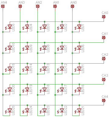
Again, on a whim, I decided to open up EaglePCB so I could create a schematic of the 5x5 matrix. I started by placing 25 LEDs on the diagram arranged in five rows and columns. I numbered them with number 1 in the top-right, number 2 to the left of 1, et cetera. I placed solder pads at the top of each column and the end of each row. Then I connected the LED cathodes of each row together and to the solder pad and labeled them ca0 to ca4. I also named each net n$c0 to n$c4. I did the same for the anodes in each column, naming them an0 to an4 and n$a0 to n$a4. I decided to name the nets to help identify the wiring on the board, once I completed the layout. With the s hematic complete I switched to the board window.
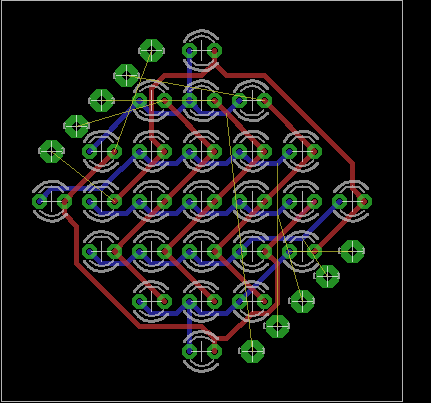
This is when my the nearly random choice of how to number the LEDs (when I modified the Animator app) became important. I realized that I had to use the same layout. So I started placing the LEDs on the board in the order. After placing them I used auto-route for the traces, but it looked messy to me. Instead I routed by hand, putting the cathode lines on one side of the boar and the anode lines on the other. I also left the segments between the LEDs and the solder pads unroluted for now, since it looked nicer. Note that I was nit planning on using this board in the short term, but it help immensely to plan the wiring.
The next thing I did was to print out the board. Actually I printed the board after the auto-routing, so the printout was rather confusing. To sort out the wiring I selected each anode net, with "show n$a0" for example, and wrote the corresponding column number in the anode pin hole of the LEDs on the net. I did the same thing for the cathode nets. Now I had a top down view of the arrangement with the rows and columns identified.
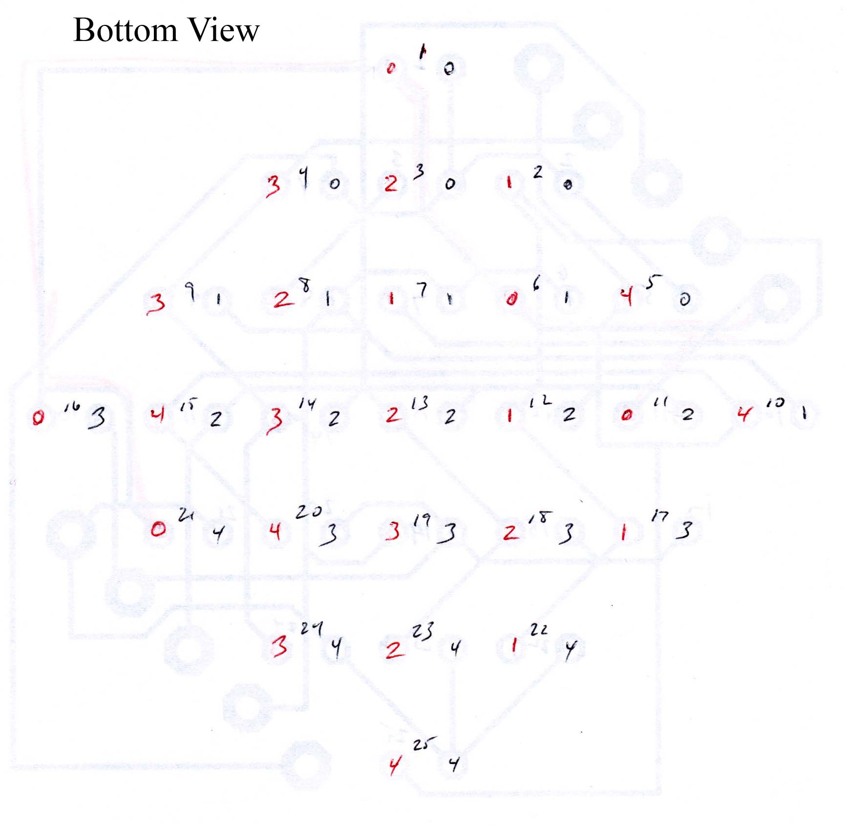
From past experience, I knew that trying to wire-wrap the LEDs from the bottom while looking at a top-down wiring diagram was going to be a problem. It is confusing and I usually make mistakes. To solve this I turned over the print out and numbered each LED. From the bottom the lower numbered LEDs in each row were on the right instead of the left. Then I copied the number from the anode and cathode pin for each LED from the front to the back. I now had a diagram that showed which cathodes to wire together and which anodes.
(Click on the picture for a full size 300dpi image.)
Building It
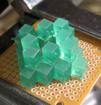
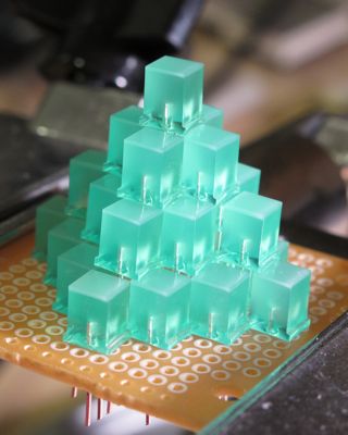
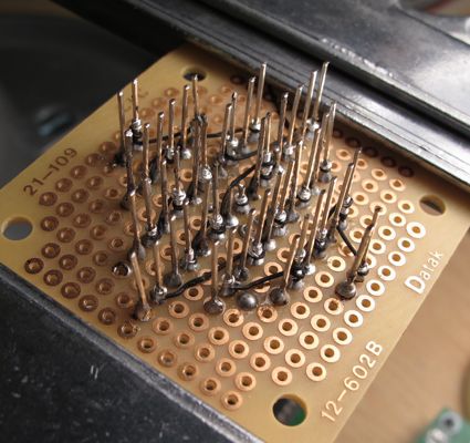
I decided to try to build it. These pictures show the progress after two rows of LEDs have been soldered to the little perf-board from RadioShack.
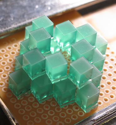
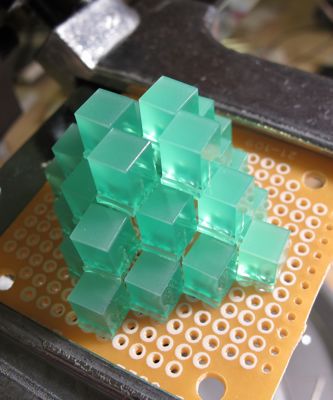
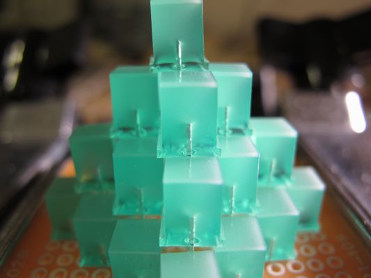
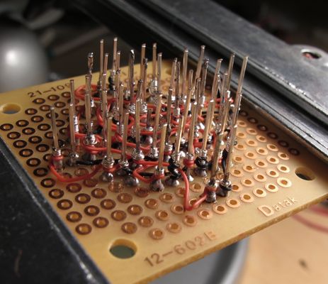
These pictures show three rows soldered. This is only four more LEDs than the previous pictures.
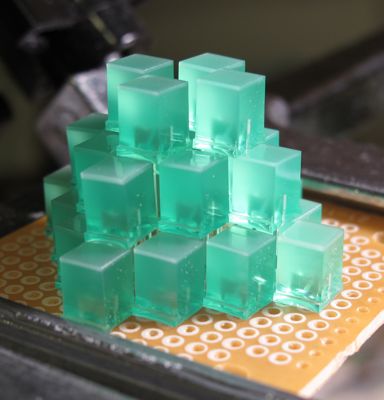
The complete LED pyramid.
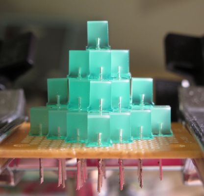
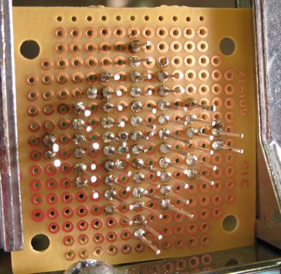
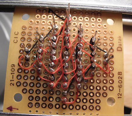
The bottom, before wire-wrapping, then wire-wrap cathode-only, finally wire-wrap cathode and anode. Note that the five row wires and five column wires for powering the LEDs are not attached yet.
Notice the arrow in the corner of the last picture. This points "up", or "north".
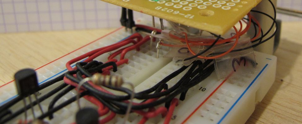
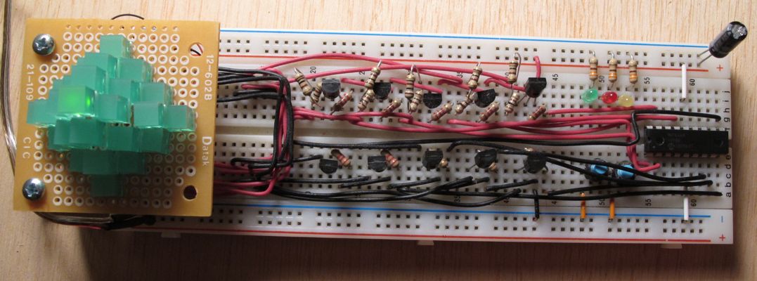
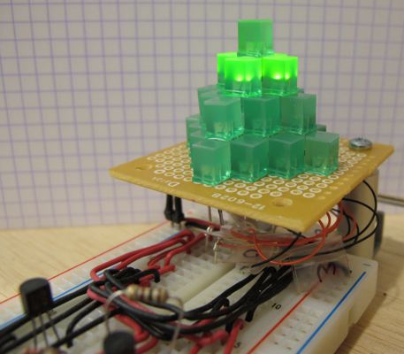
Breadboard
I used a breadboard I had on the workbench that I initial put together for the FiveSquare project. I usually leave these things around because I never know when I will use them again. The first picture shows the row and column wires attached to the pyramid. These are the wires with the numbered pieces of tape. I realized that numbering the wires would make it a lot easier when plugging the wires into the breadboard. To make it easier to plug the wire-wrap wires into the breadboard, I use the leads I cut off from the LEDs, bend the end over to form a small loop, and wrap the wire around the lead. I tried to show this in the first picture. I also put some spacers on the end of the board so I could keep the board level and slightly over the breadboard.
(You can click on the next three pictures to show them twice as large.)

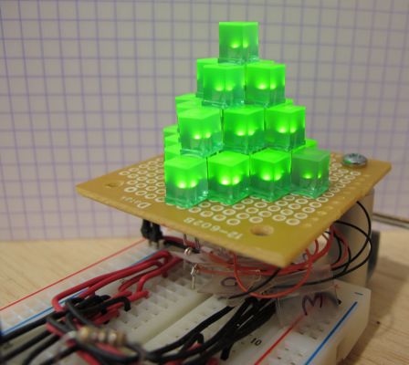
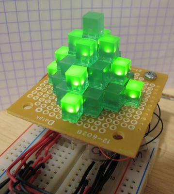
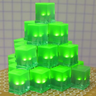
Illuminated!
Here are some photos of the LEDs lit-up.
Programming
The FiveSquare code worked without any changes, so I did not need to do any more coding to get this work.
Odds and Ends
This looks like a very small Four-Sided Pyramid, by Sol LeWitt.